Mega32U4 with A7 GSM GPRS GPS Module

Elecrow Mega32U4 with A7 GSM GPRS GPS Module A6 A6C
DIY Kit Newest Development Board Integrated Circuits GPS GSM Antenna
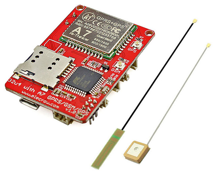
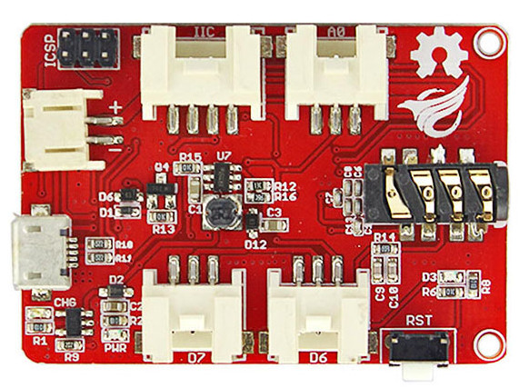
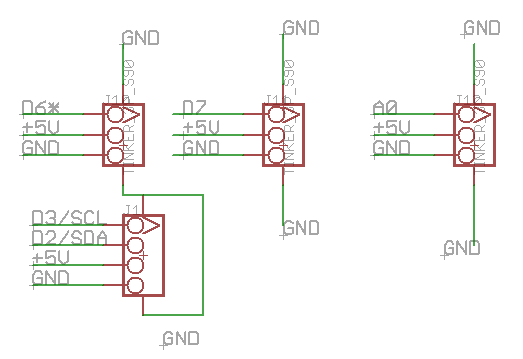
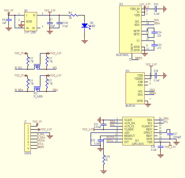
Схема32u4 with A7 GPRS GSM GPS v1.0

The new 32U4 with A7 GSM/GPRS/GPS Board is based on mega32U4 and A7 GSM/GPRS/GPS module. Compare to 32u4 with A6 GPRS GSM Board, it adds a GPS function,it also can call and send text message even via GPRS to upload data to server. At the same time it leads to an analog interface, an IIC interface and 2 digital interface. which you can connect to other module more easily.
Remote control and data acquisition will be more convenient.It is worth mentioning that this module can be powered by battery, and comes with a battery charging circuit, some IOT projects will make it take a leading role.
Add three GPS commands as follows:
AT+GPS=1 :OPEN GPS function
AT+GPSRD=1 : Get GPS information
AT+GPS=0: Close GPS function

Features

32U4 combine with A7 module
Multiple interfaces
3.7V Battery power supply
GSM/GPRS/GSM function
Support the GSM / GPRS four bands, including 850,900,1800,1900MHZ
Support China Mobile and China Unicom’s 2G GSM network worldwide
GPRS Class 10
Support GPS and AGPS
Support ROHS, FCC, CE, CTA certification
Specifications

Operating temperature -30 ℃ to + 80 ℃
Operating Voltage 3.3V-4.2V
Sensitivity <-105
Standby average current 3ma less
Working Voltage:3.7V
Sizes: 50mm x 35mm
Package list

32u4 with A7 GPRS/GSM/GPS Board x1
GSM antenna x 1
GPS antenna x 1

Wiki & External links

Купить в Aliexpress.

GY-87 MPU6050 HMC5883L BMP180 Модуль

987654321

  • 10DOF modules (three-axis gyroscope + triaxial accelerometer and three-axis magnetic field + atmospheric pressure)
  • Means of communication: IIC Communication protocol(fully compatible with 3-5V system containing LLC circuit)
  • Acceleration,Gyroscope and magnetometer
  • chip:MPU6050+HMC5883+BMP180
  • power supply :3.3V-5V
  • size:2.2cmx1.7cm

qwertyuiop 1234567890

Описание.

Для включения компаса HMC5883L нужно следующие.
// Bypass Mode
Wire.beginTransmission(0x68); // Address of MPU5060
Wire.write(0x37);
Wire.write(0x02);
Wire.endTransmission();

Wire.beginTransmission(0x68);
Wire.write(0x6A);
Wire.write(0x00);
Wire.endTransmission();

// Disable Sleep Mode
Wire.beginTransmission(0x68);
Wire.write(0x6B);
Wire.write(0x00);
Wire.endTransmission();

Arduino ATmega 2560 16AU + CP2102 (USB to UART)


2560-arduino-home-made

Вот решил Arduino собрать на ATmega2560, вот что получилось.

p.s. Плата переходник для подключения WG12864B

U8GLIB_KS0108_128 u8g(22,23,24,25,26,27,28,29,34,30,39,33,32,31);

// 8Bit Com: D0..D7: 8,9,10,11,4,5,6,7 en=18, cs1=14, cs2=15,di=17,rw=16,rst=31

Тест программка.

#include <openGLCD.h>

void setup()
{
  GLCD.Init();
  GLCD.SelectFont(System5x7);
  GLCD.ClearScreen();

  pinMode(A15, OUTPUT);
  pinMode(44, OUTPUT);
  digitalWrite(44, HIGH);    
  digitalWrite(A15,HIGH);
}

byte pos = 0;
byte r;
void loop()
{
  while(1) {
    GLCD.ClearScreen();

    for(byte x=0;x<11;x++) {
      r = random(1,63);
      if (pos==0) {
        Bar(pos,0,10,r);
      }
      else {
        Bar(pos+(x*2),0,10,r);
      }
      pos=pos+10;
    }
    delay(200);
    pos =0;
  }

}

void Bar(int x,int y, int w, int h) {
  GLCD.FillRect(x,63-h,w,h,BLACK);
}