Робот для Сумо на FRDM-KL25Z (Версия 2.0)

Из чего все это собирается:

kl25zumoNewOneforSumoMini

Продолжаем строить. Блок управления двигателями.  L298P + LC74H00.

OLYMPUS DIGITAL CAMERA OLYMPUS DIGITAL CAMERA OLYMPUS DIGITAL CAMERA

Первую часть собрали, драйвер двигателей. L298P


OLYMPUS DIGITAL CAMERA OLYMPUS DIGITAL CAMERA

Статья про драйвер моторов L298

Zumo Сумо на FRDM-KL05Z и платформе ZUMO

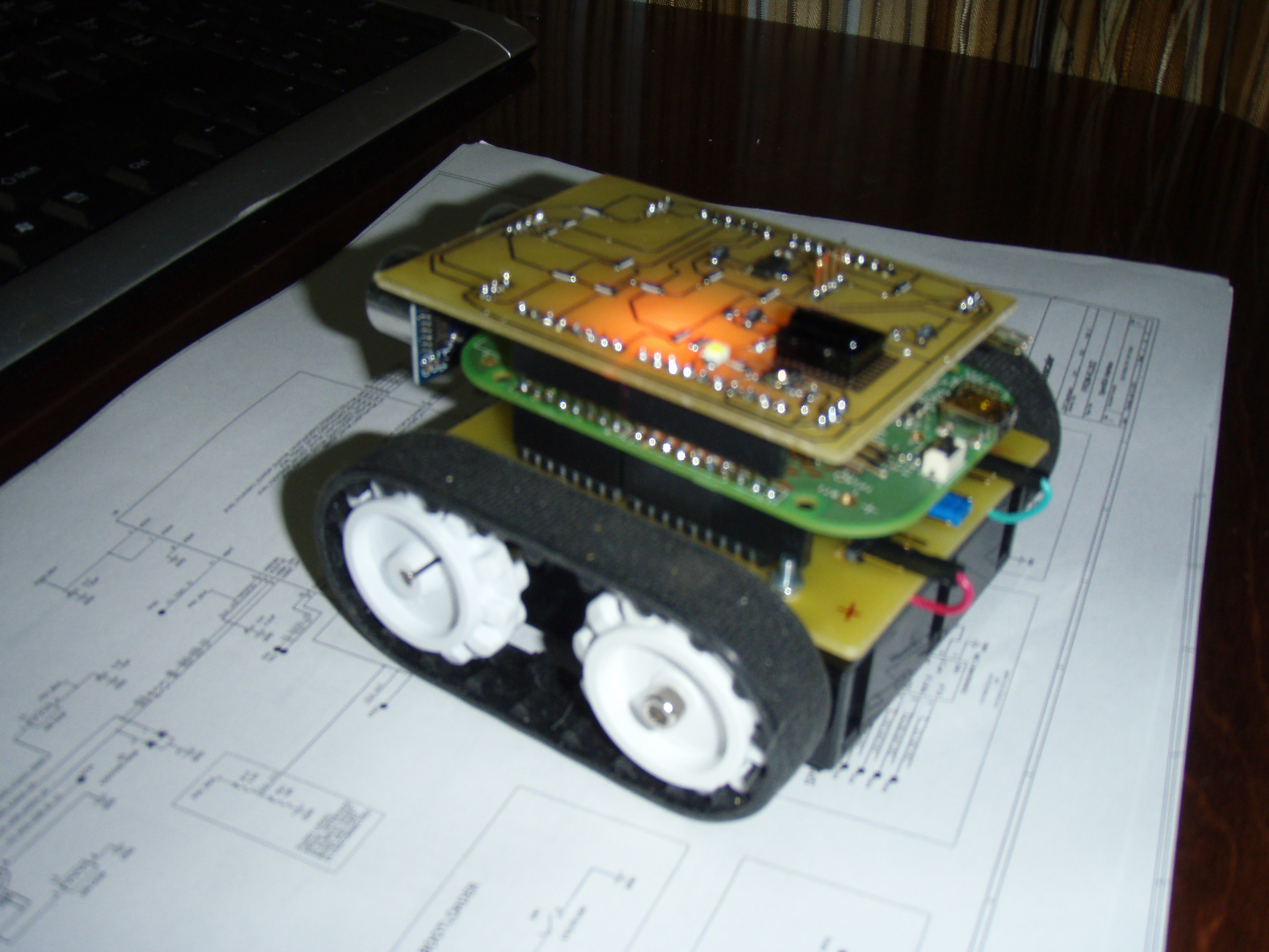
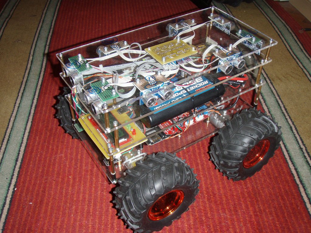
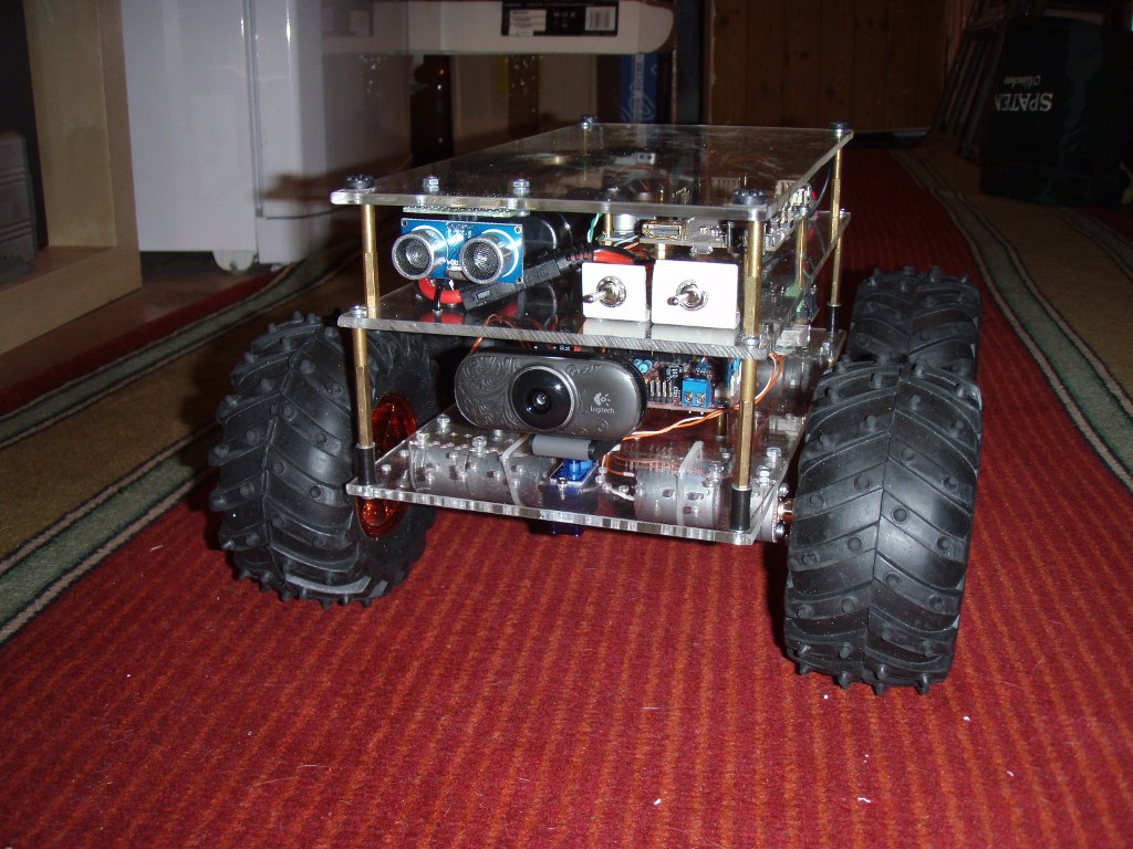
И так начинаем строить робота для соревнований по мини сумо.
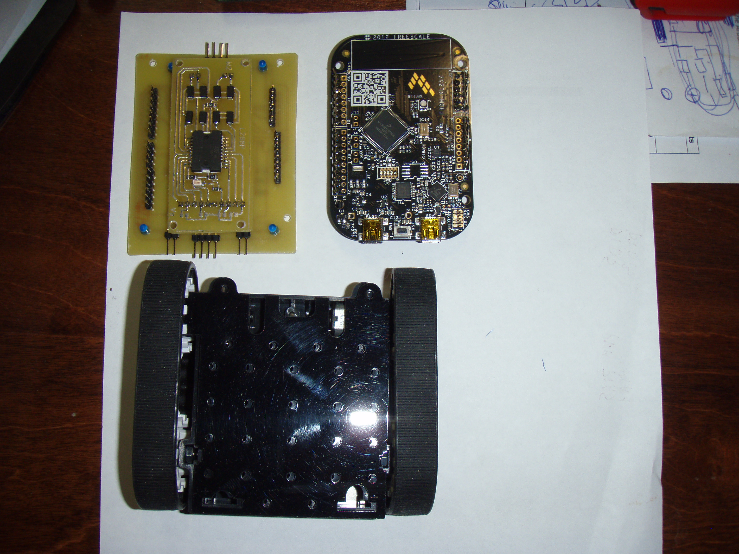
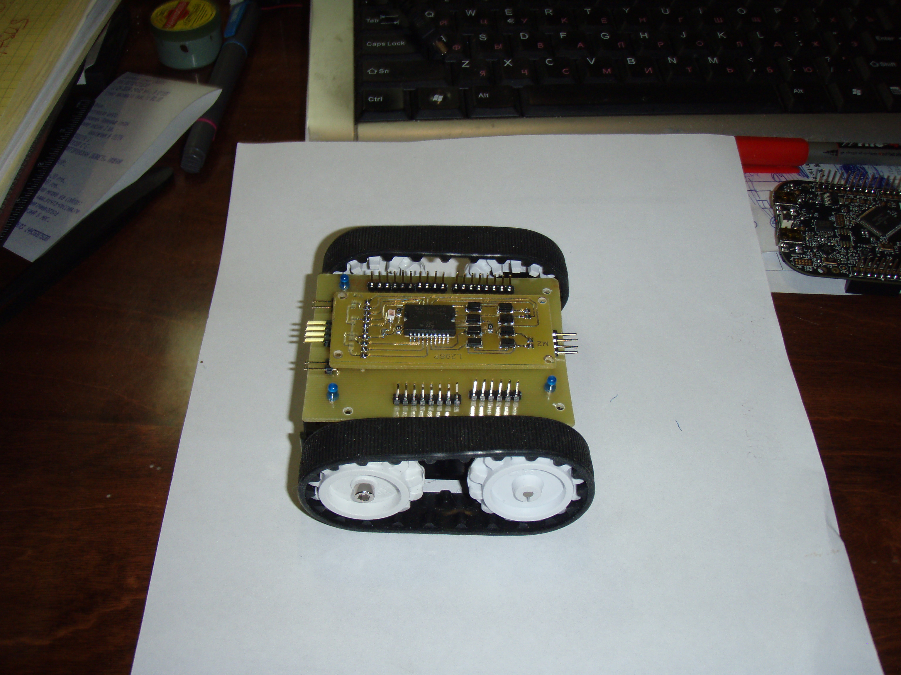
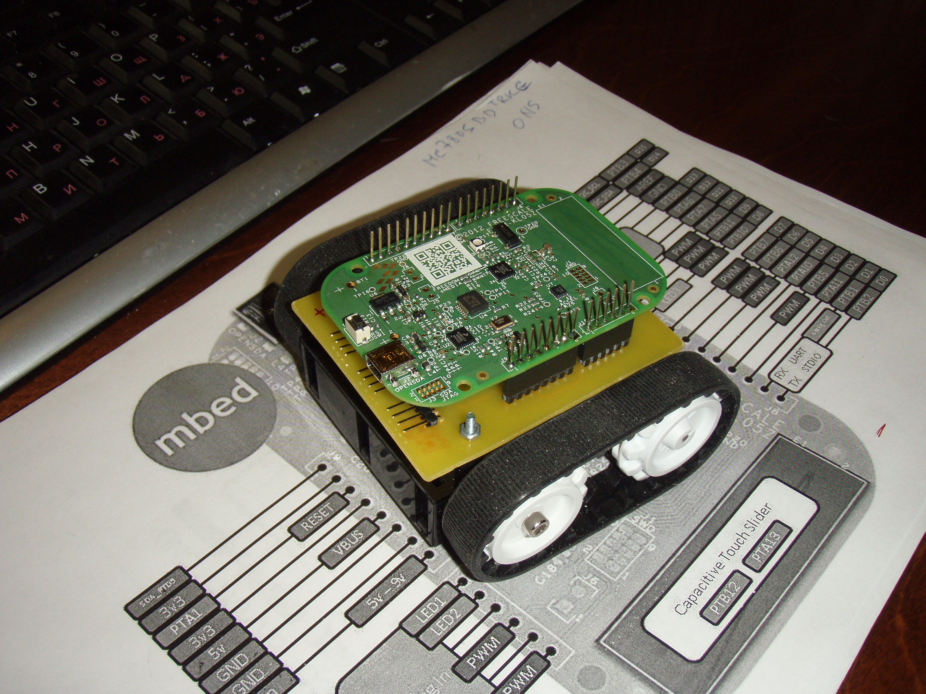
Пока только первый этап, это контролер и шасси с двигателями.
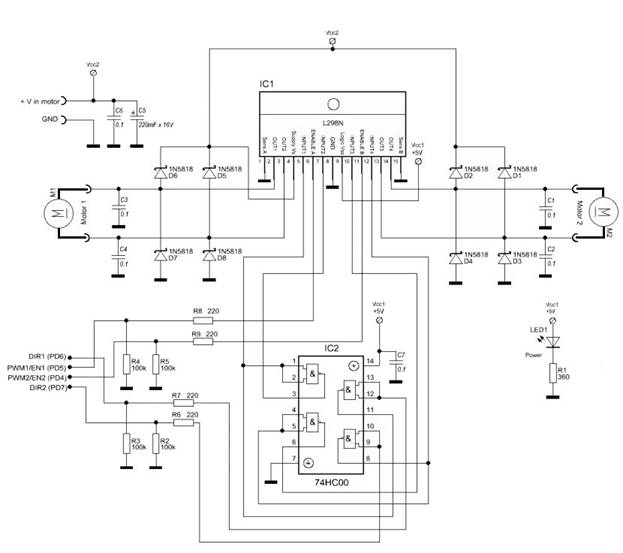
Драйвер моторов: Motor Driver 1A Dual TB6612FNG
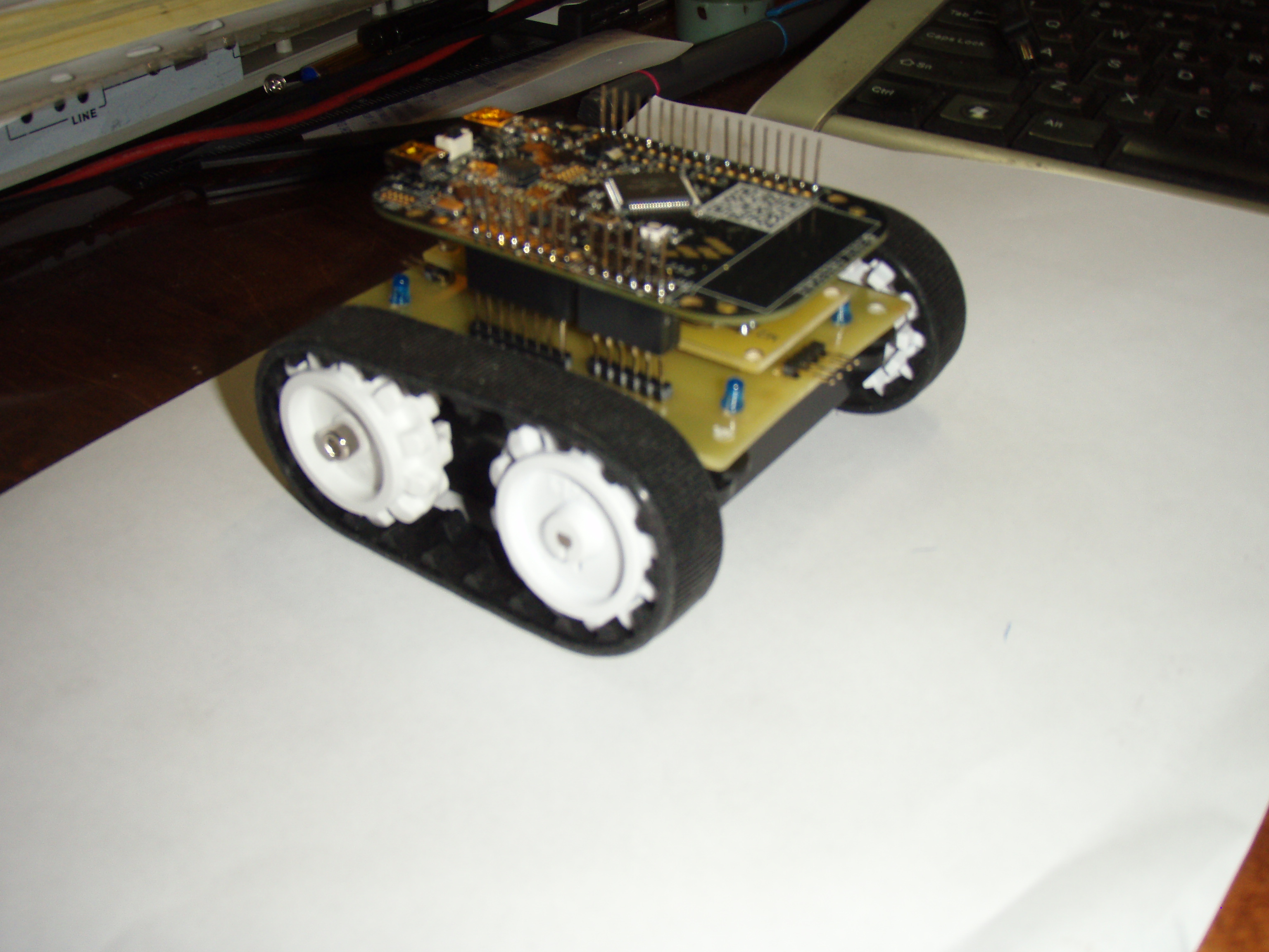
Контролер: FRDM-KL05Z
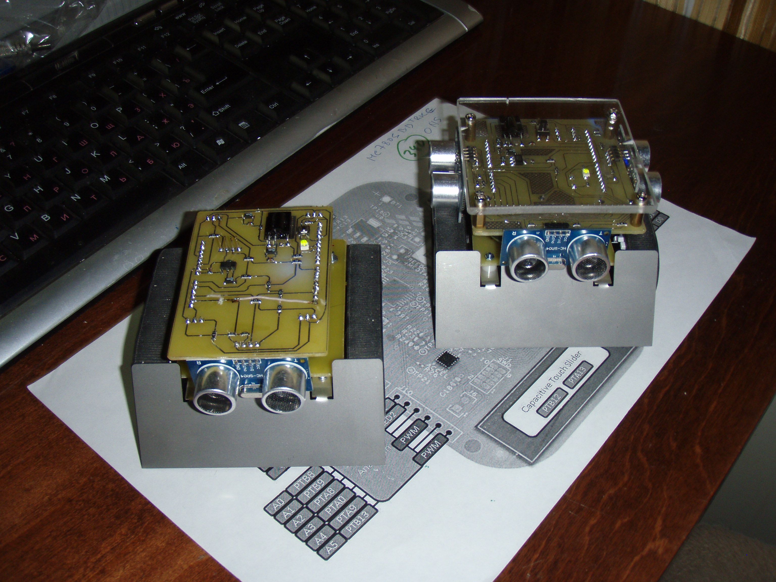
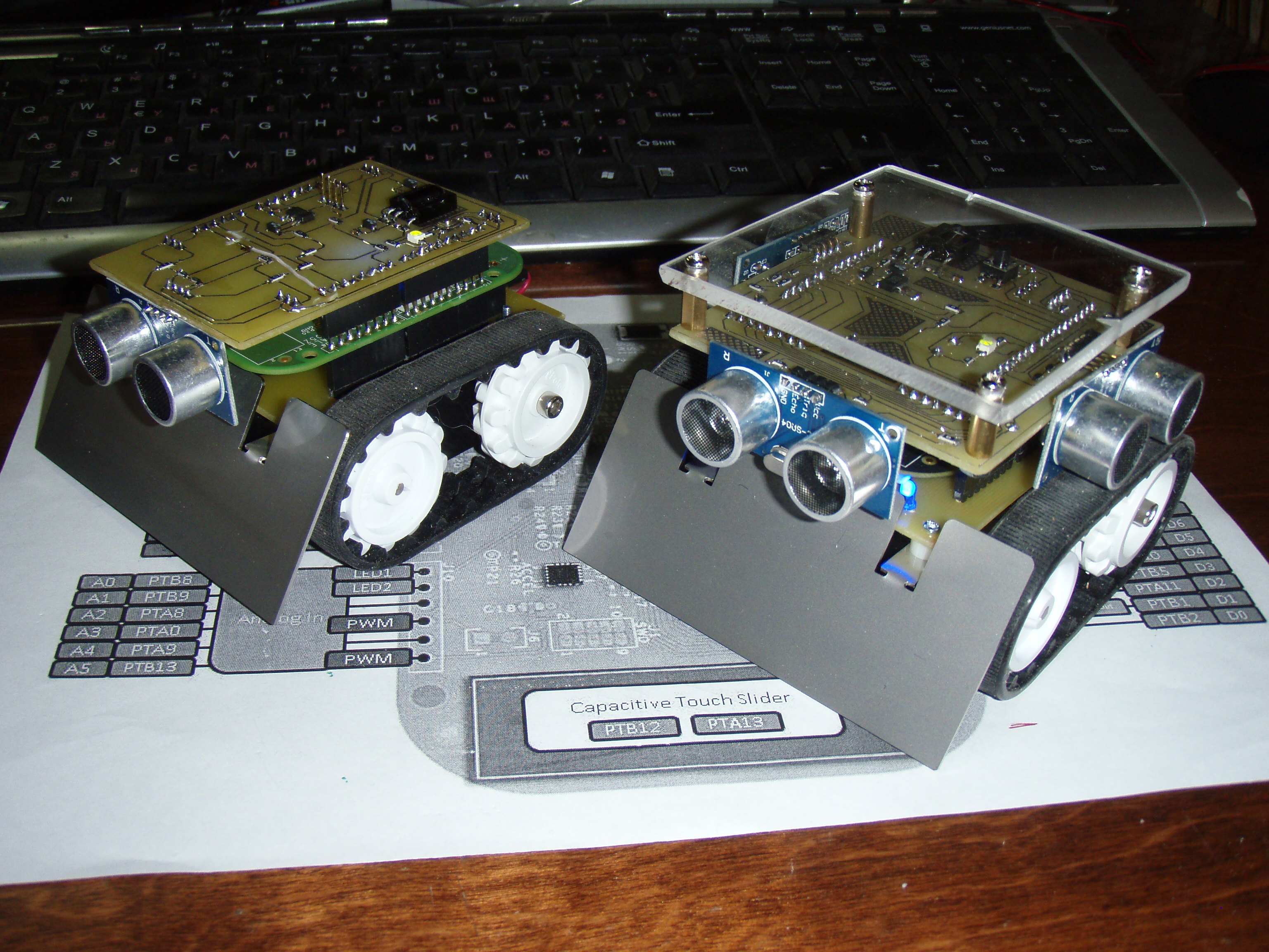
Шасси ZUMO.

Вес с батарейками 247 г.

OLYMPUS DIGITAL CAMERA

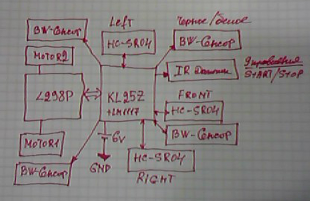
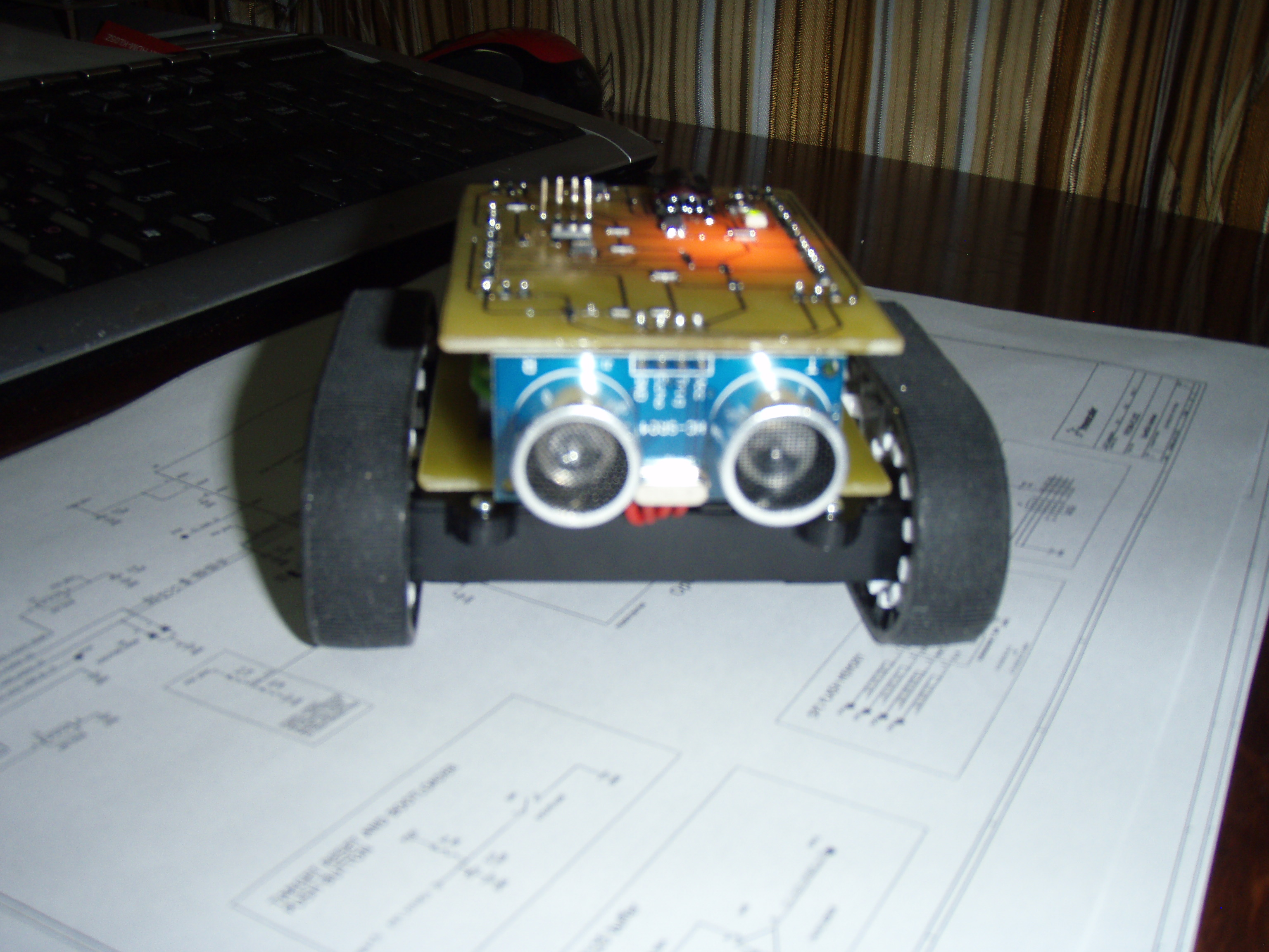
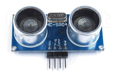
Добавили плату с датчиками:

hc-sr04 TSOP31238

OLYMPUS DIGITAL CAMERA OLYMPUS DIGITAL CAMERA OLYMPUS DIGITAL CAMERA

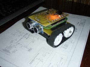
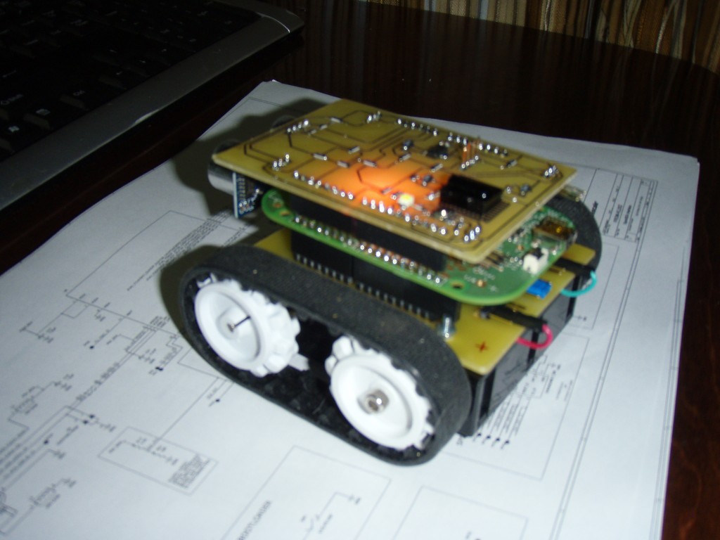
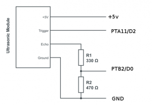
Схема подключения HC-SR04 к FRDM-KL05Z

Ultrasonic-Module-Circuit-KL05z


/* Test */

#include "mbed.h"
#include "ReceiverIR.h"

// PinName const SDA = PTB4;
// PinName const SCL = PTB3;

// --------------- Верхний Уровень -------------------------------

// A5 BW-Sense - FRONT
// A3 BW-Sense - FRONT

// A1 BW-Sense - REAR
// A0 BW-Sense - REAR

float getRange();

void falling(void);
void rising(void);

DigitalOut trig(D2); // Triger for HC-SR04
InterruptIn echo(D0); // D0

Timer tmr;

int delay = 0;
float range = 0.0;

// DigitalIn sStart(D7) // Signal for Start and Running
// DigitalIn IR(D11) // Input from IR Receiver

// DigitalIn But(D13); // Buttom 1-Press (0-Down)

DigitalOut mLED(D12); // LED

ReceiverIR ir_rx(D11);

// --------------- Нижний уровень --------------------------------

// Motor B

PwmOut PWMB(D10); //Speed control
DigitalOut BIN1(D8); //Direction
DigitalOut BIN2(D9); //Direction

DigitalOut STBY(D6) ; //standby

//Motor A

PwmOut PWMA(D3); // Speed control
DigitalOut AIN1(D5); // Direction
DigitalOut AIN2(D4); // Direction

void move(int motor, float speed, int direction);

void stop();
void forward();
void reverse();
void left();
void right();

#define STOP 0
#define FORWARD 1

int COMMAND = STOP;

void rising(void)
{
tmr.reset();
tmr.start();
}

// Stop and read the timer at the end of the pulse

void falling(void)
{
tmr.stop();
delay = tmr.read_us();
}

float getRange()
{
// send a trigger pulse, 20uS long
trig = 1;
// wait (0.000002);
wait_us(10);
trig = 0;

// Timer starts on rising edge of echo
// Timer stopped and read on falling edge
// wait 50ms as a time out (there might be no echos)

wait(0.050);

return delay/58.0;
}

int main(void)
{

STBY = 0; // Моторы Выключены
mLED = 1;

// RemoteIR::Format format;
// int bitcount;
// uint8_t buf[32];

echo.rise(&rising);
echo.fall(&falling);

while (true) {

// if (ir_rx.getState() == ReceiverIR::Received) {
// bitcount = ir_rx.getData(&format, buf, sizeof(buf) * 8);
// for(int i=0; i<sizeof(buf); i++) printf("%0X ",buf[i]);
// printf("\n%d\n",bitcount);
// }

printf("%f\n",getRange()); // Печатать расстояние от HC-SR04

wait(0.5);
mLED = !mLED;
wait(0.5);

}
}

void move(int motor, float speed, int direction)
{

// Move specific motor at speed and direction
// motor: 0 for B 1 for A
// speed: 0 is off, and 255 is full speed
// direction: 0 clockwise, 1 counter-clockwise

STBY = 1; //disable standby

int inPin1 = 1;
int inPin2 = 0;

if(direction == 1) {
inPin1 = 0;
inPin2 = 1;
}

if(motor == 1) {
AIN1 = inPin1;
AIN2 = inPin2;
PWMA = speed;
} else {
BIN1 = inPin1;
BIN2 = inPin2;
PWMB = speed;
}
}

void stop()
{
STBY = 0; // enable standby

AIN1 = 0;
AIN2 = 0;
PWMA = 0.0;
BIN1 = 0;
BIN2 = 0;
PWMB = 0.0;
}

void forward()
{
move(1, 1.0, 0); //motor 1, full speed, left
move(2, 1.0, 1); //motor 2, full speed, left
}

void reverse()
{
move(1, 1.0, 1); //motor 1, full speed, left
move(2, 1.0, 0); //motor 2, full speed, left
}

void left()
{
move(1, 0.5, 1); //motor 1, full speed, left
move(2, 0.5, 1); //motor 2, full speed, left
}

void right()
{
move(1, 0.5, 0); //motor 1, full speed, left
move(2, 0.5, 0); //motor 2, full speed, left
}

Что нужно сделать в другой версии: (To DO)

  • Мало индикации
  • Мало кнопок управления, все только через IR
  • Sharp GP2D12 (от 0 до 130 см)

NewPing Library for Arduino (Ultrasonic Sensors)

hc-sr04-500x500

Пример:

// ---------------------------------------------------------------------------
// This example code was used to successfully communicate with 15 ultrasonic sensors. You can adjust
// the number of sensors in your project by changing SONAR_NUM and the number of NewPing objects in the
// "sonar" array. You also need to change the pins for each sensor for the NewPing objects. Each sensor
// is pinged at 33ms intervals. So, one cycle of all sensors takes 495ms (33 * 15 = 495ms). The results
// are sent to the "oneSensorCycle" function which currently just displays the distance data. Your project
// would normally process the sensor results in this function (for example, decide if a robot needs to
// turn and call the turn function). Keep in mind this example is event-driven. Your complete sketch needs
// to be written so there's no "delay" commands and the loop() cycles at faster than a 33ms rate. If other
// processes take longer than 33ms, you'll need to increase PING_INTERVAL so it doesn't get behind.
// ---------------------------------------------------------------------------
#include "NewPing.h"

#define SONAR_NUM     8 // Number or sensors.
#define MAX_DISTANCE 200 // Maximum distance (in cm) to ping.
#define PING_INTERVAL 33 // Milliseconds between sensor pings (29ms is about the min to avoid cross-sensor echo).

unsigned long pingTimer[SONAR_NUM]; // Holds the times when the next ping should happen for each sensor.
unsigned int cm[SONAR_NUM];         // Where the ping distances are stored.
uint8_t currentSensor = 0;          // Keeps track of which sensor is active.

NewPing sonar[SONAR_NUM] = {       //   Sensor object array. Each sensor's trigger pin, echo pin, and max distance to ping.
  NewPing(50, 51, MAX_DISTANCE),   // 1
  NewPing(52, 53, MAX_DISTANCE),   // 2
  NewPing(38, 37, MAX_DISTANCE),   // 3
  NewPing(40, 39, MAX_DISTANCE),   // 4
  NewPing(33, 34, MAX_DISTANCE),   // 5
  NewPing(35, 36, MAX_DISTANCE),   // 6
  NewPing(24, 25, MAX_DISTANCE),   // 7
  NewPing(26, 27, MAX_DISTANCE),   // 8
};

void setup() {
  
  Serial1.begin(115200);
  
  pingTimer[0] = millis() + 75;           // First ping starts at 75ms, gives time for the Arduino to chill before starting.

  for (uint8_t i = 1; i < SONAR_NUM; i++) // Set the starting time for each sensor.
    pingTimer[i] = pingTimer[i - 1] + PING_INTERVAL;
}

void loop() {
  
  for (uint8_t i = 0; i < SONAR_NUM; i++) {       // Loop through all the sensors.
    if (millis() >= pingTimer[i]) {               // Is it this sensor's time to ping?
      pingTimer[i] += PING_INTERVAL * SONAR_NUM;  // Set next time this sensor will be pinged.
      if (i == 0 && currentSensor == SONAR_NUM - 1) oneSensorCycle(); // Sensor ping cycle complete, do something with the results.
      sonar[currentSensor].timer_stop();          // Make sure previous timer is canceled before starting a new ping (insurance).
      currentSensor = i;                          // Sensor being accessed.
      cm[currentSensor] = 0;                      // Make distance zero in case there's no ping echo for this sensor.
      sonar[currentSensor].ping_timer(echoCheck); // Do the ping (processing continues, interrupt will call echoCheck to look for echo).
    }
  }
  // The rest of your code would go here.
}

void echoCheck() { // If ping received, set the sensor distance to array.
  if (sonar[currentSensor].check_timer())
    cm[currentSensor] = sonar[currentSensor].ping_result / US_ROUNDTRIP_CM;
}

void oneSensorCycle() { // Sensor ping cycle complete, do something with the results.

  for (uint8_t i = 0; i < SONAR_NUM; i++) {
    Serial1.print(i);
    Serial1.print("=");
    Serial1.print(cm[i]);
    Serial1.print("cm ");
  }

  Serial1.println();
}

X-Rover 4.0

В процессе программирования возникли некоторые трудности, которые оказались связанные с ошибкой сборки. Решил все перебрать, улучшить конструкцию для сборки и разборки, а также для того чтобы было удобно добавлять необходимые датчики. Также заменили камеру, установили более удобную и более качественную, также установил серво-привод  для вращения камерой.

Теперь программировать и добавлять того чего захочется.

X-Rover 4.0 OLYMPUS DIGITAL CAMERA OLYMPUS DIGITAL CAMERA